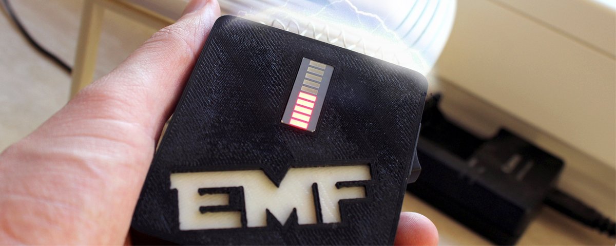
EMF Detector: Let's hunt some ghosts!
The idea to build an EMF-Detector came while i fucked up my last project partially. While i was soldering the pcb i did a mistake while connecting a wire. This gave me a broken signal of a buttonstate (switching from 0 to 1) switching back and forth. I fixed that, but wanted to know exactly why this happens.
Result: When you don't connect the input of the controller to ground, you are not able to set a solid state and the µController starts to interpret everything what he gets. In this case it reads electromagnetic fields. So why not digging further into this and build a gauge to have a look on which devices are having a nice electromagnetic party?
The plan was to build this just in a short amount of time. Just in one week after work. But like always, the days passed by + a weekender and at the end it took some weeks. Mostly it took so long, because i failed the most of the time...
I used two projects as templates:
- The detector built by (Aaron ALAI)
- The advanced detector built by Collin Cunningham for Makezine (Youtube Video)
Both projects were built in 2009. Seven years later I start to build one, too. Mhm. Unfortunately I was always a bit slower then others.
Here comes the BOM:
- Arduino (to prototype)
- Breadboard
- 9v Block
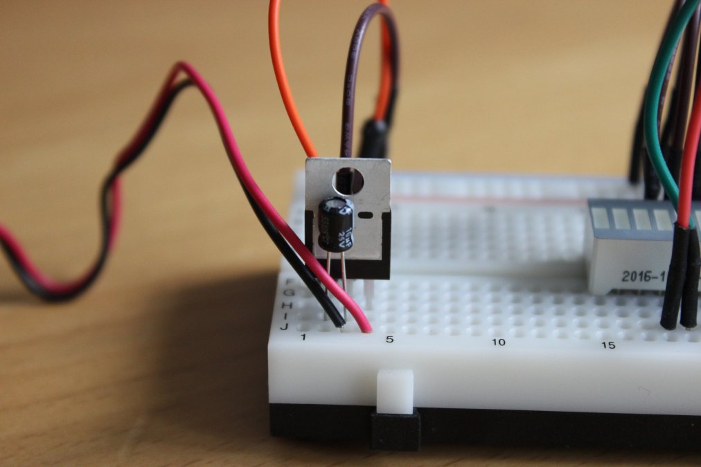
- Voltage regulator (7805 something to get from 9V to 5V)
- 2 Capacitors (10µF and 0,1µF)
- 10 Leds (maybe thisBargraph)
- 10 x 330Ohm resistors
- 1 x 3,3mOhm resistor
- little bit of wire (ca. 15cm)
Because i wanted it this way, i removed the Arduino after prototyping and flashed my written code directly onto an µController. This saved some space and power (and looks more professionally, but i destroyed this look by my unbelievable soldering skills).
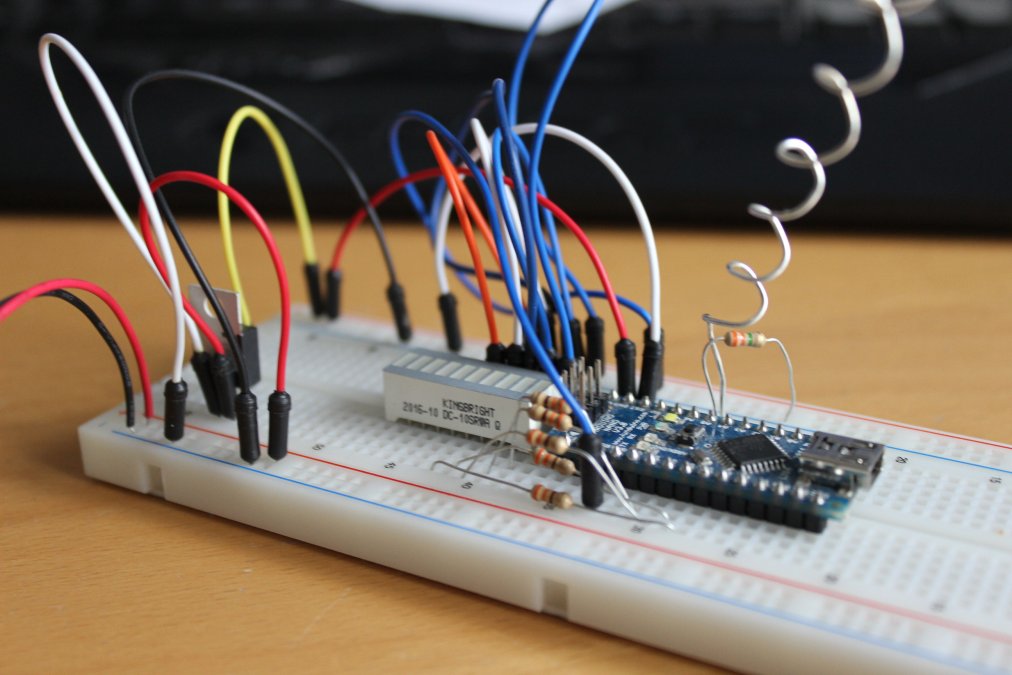
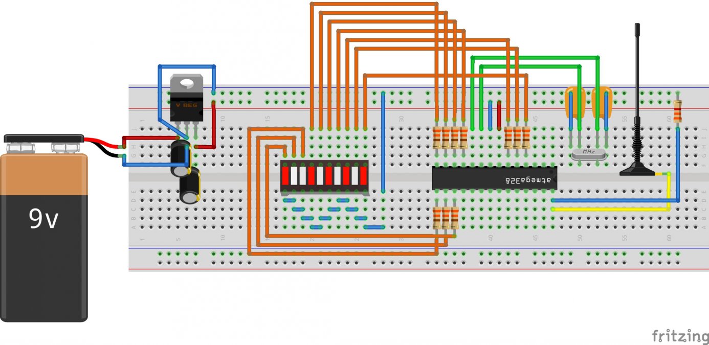
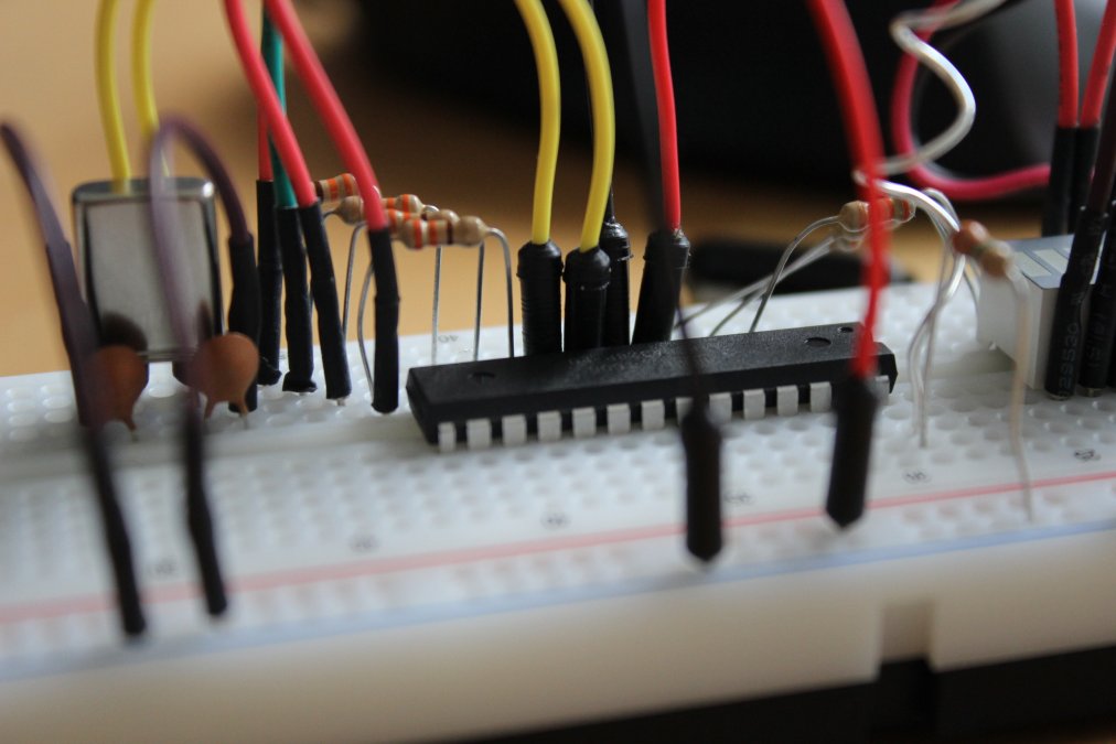
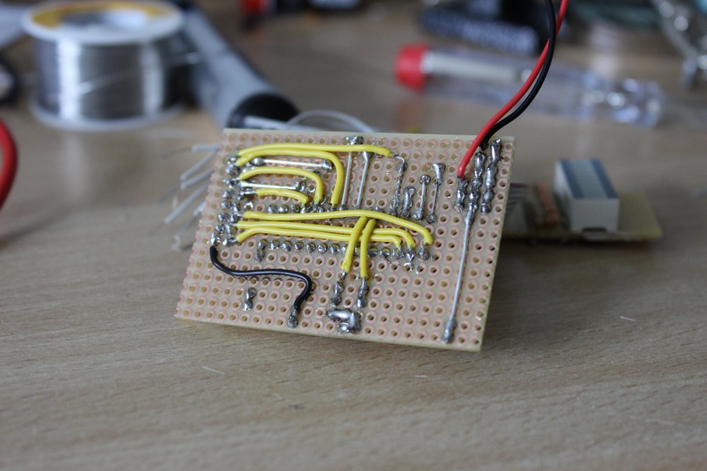
So. There is no black voodoo magic: The schema should look like this, or however you want it. But mine looks like this:
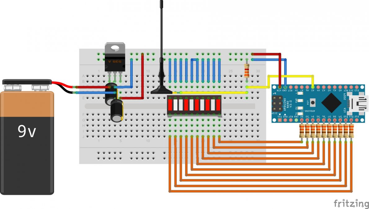
Just connect the LEDs to the digital outputs 02-11 (Don't forget the 330Ohm resistors in between!) and some wire (antenna) between A5 and a 3,3mOhm resistor, which has to be connected with ground.
Maybe some of you will realize, you normally would use 220Ohm resistors. You're right, but when all LEDs light up, they will run with 220mA. This is the absolute limit, the controller can handle. So I decided to use bigger resistors. Haha! Jep! I'm a smart dude!
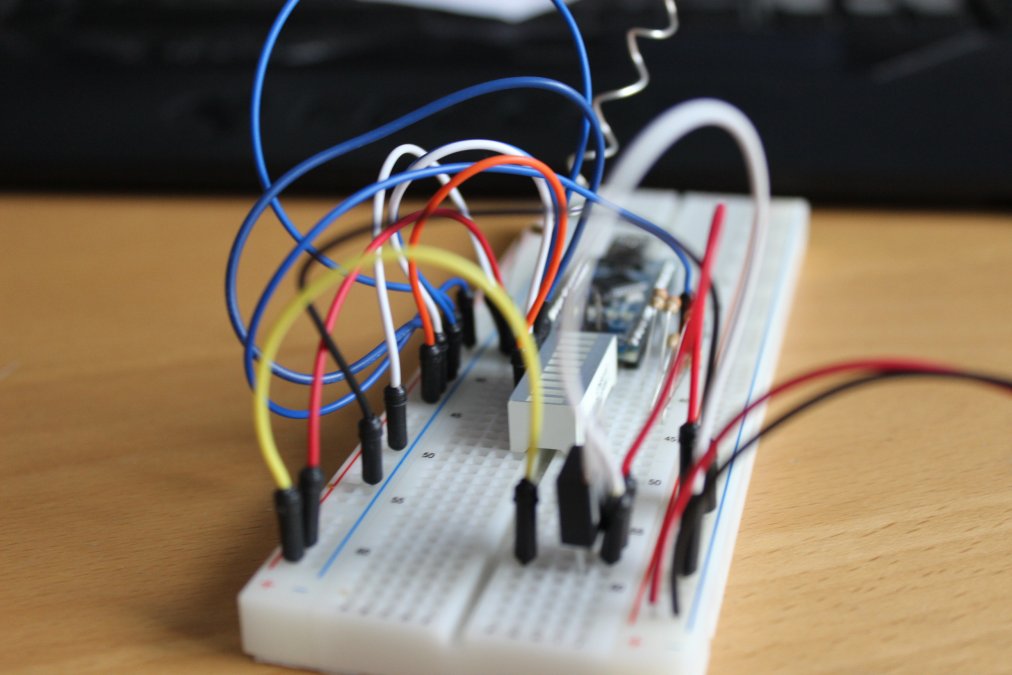
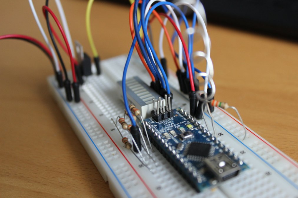
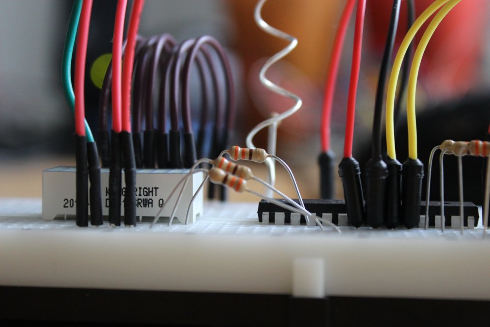
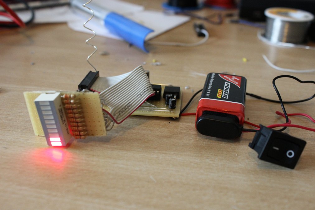
So it should looke similar to this:

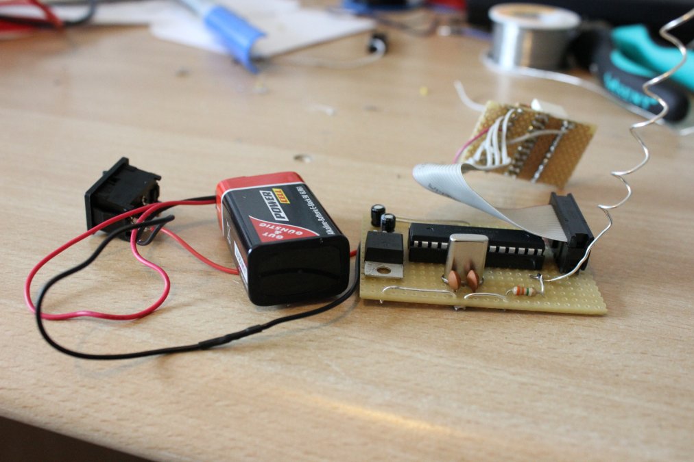
If you have the same idea like me, to use an Atmel instead of an Arduino, you need some more parts:
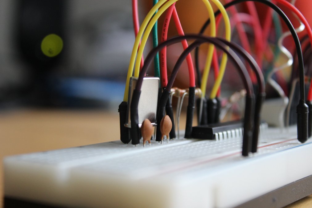
- 1x 16MHz crystal
- 2 x 18µF Capacitor
Connect the capacitors from ground to each pin of the crystal and the crystal to (Pin 9 and 19) of the controller.
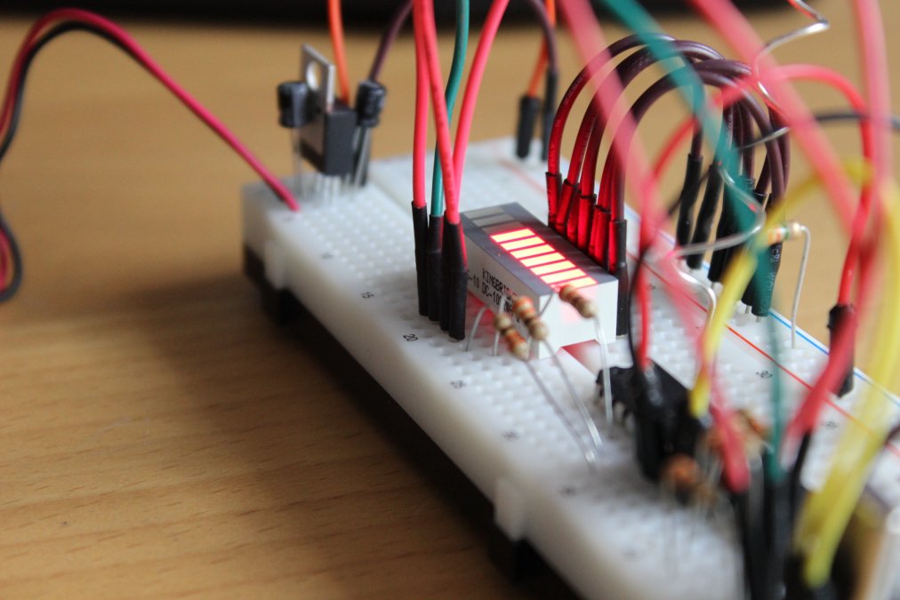
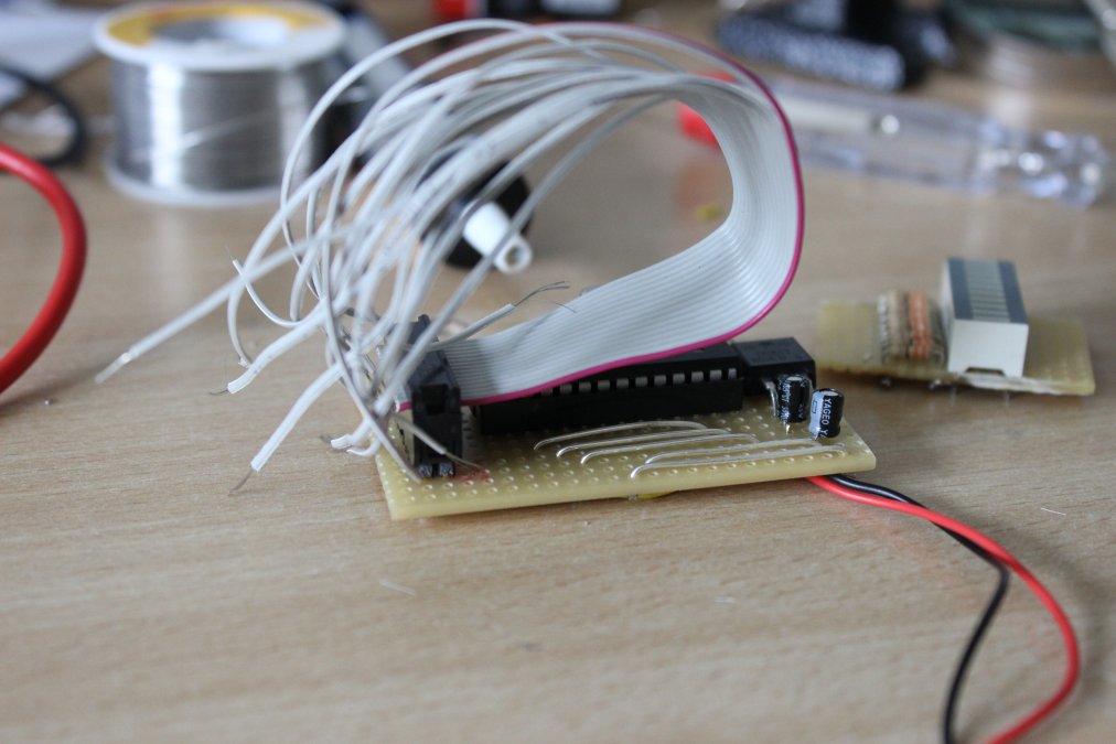
Nearly exactly like this:
Hint: You should connect the antenna as far as possible from the LEDs. It's possible to measure yourself. You won't do that. Would be stupid.
The code I'm using is based on the two projectes, mentioned above. I just shortened and tidied it up a bit:
/* EMF Detector for LED Bargraph v1.0
original code/project by Aaron ALAI - aaronalai1 ät gmail punked com
modified for use w/ LED bargraph by Collin Cunningham - collin ät makezine punked com
shortened and refactored by Christian Figge - info ät flazer punked net (flazer.com)

Info:
Use IOPins 02 - 12 for LED-Bargraph
*/

#define MEASURES 15
int senseLimit = 15;
int antenna = A5;
int ranges[] = {50, 150, 250, 350, 450, 550, 650, 750, 850, 950};

int ledcount = sizeof(ranges)/sizeof(int); //same size as values in ranges (10)
int ledPinOffset = 2; //offset of starting pinout number
int bucket[MEASURES]; //bucket of values
int total = 0;
int pos   = 0;
int avg   = 0;
int val   = 0;

void setup() {
  Serial.begin(9600);
  pinMode(antenna, INPUT);
  for (int i=ledPinOffset; i<ledcount+ledPinOffset; i++) {
    pinMode(i, OUTPUT);
  }

  for (int i=0; i<MEASURES; i++) {
    bucket[i] = 0;
  }
}

void loop() {
  val = analogRead(antenna);
  if (val >= 1){
    val = constrain(val, 1, senseLimit);
    val = map(val, 1, senseLimit, 1, 1023);
    total -= bucket[pos];
    bucket[pos] = val;
    total += bucket[pos];
    pos = (pos + 1);

    if (pos >= MEASURES) {
      pos = 0;
    }
    avg = total / MEASURES;

    for (int i=0; i<ledcount; i++) {
      if (avg > ranges[i]) {
        digitalWrite(i+ledPinOffset, HIGH);
      } else {
        digitalWrite(i+ledPinOffset, LOW);
      }
    }
    Serial.println(val);
  }
}
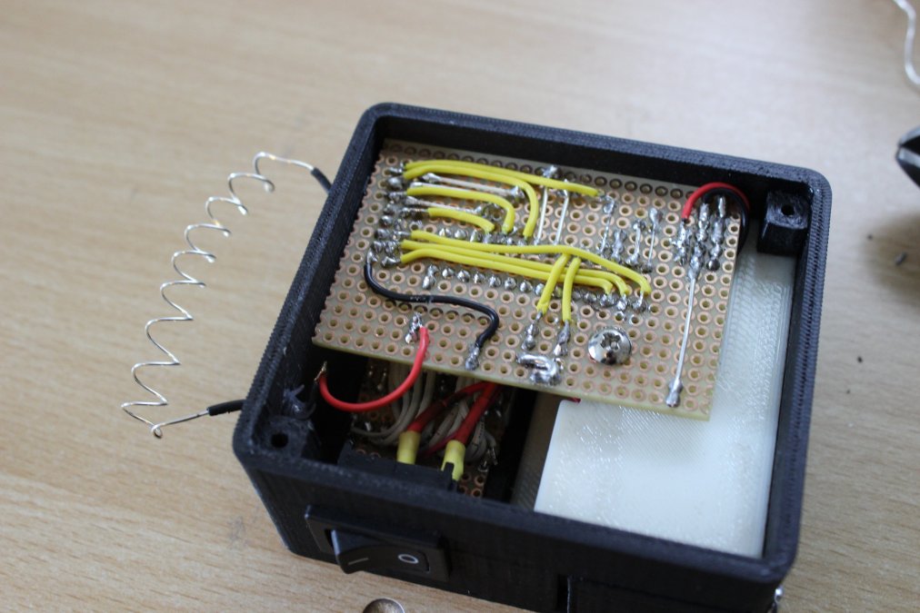
In the end i had to realize, it would make more sense, to build the hardware first and write the software afterwards, instead like I did. I had to solder really strange connections and ways, to get it work with the code i wrote. (I would have used different pins).
I really have no idea, how all the professionals worldwide are handling this: If they make compromises in hardware- AND softwaredesign, so both parts have to deal with some workarounds, or if only one of both sides have to deal with a big pile of shit.
Both ideas are bad: Either both projects will be some kind of "meeeh", or one project is awesome and the other is NOT.
Maybe someday, someone, who's into this, will read this article: Please, Please, share your knowlegde!
My soldered hardware looks like this:
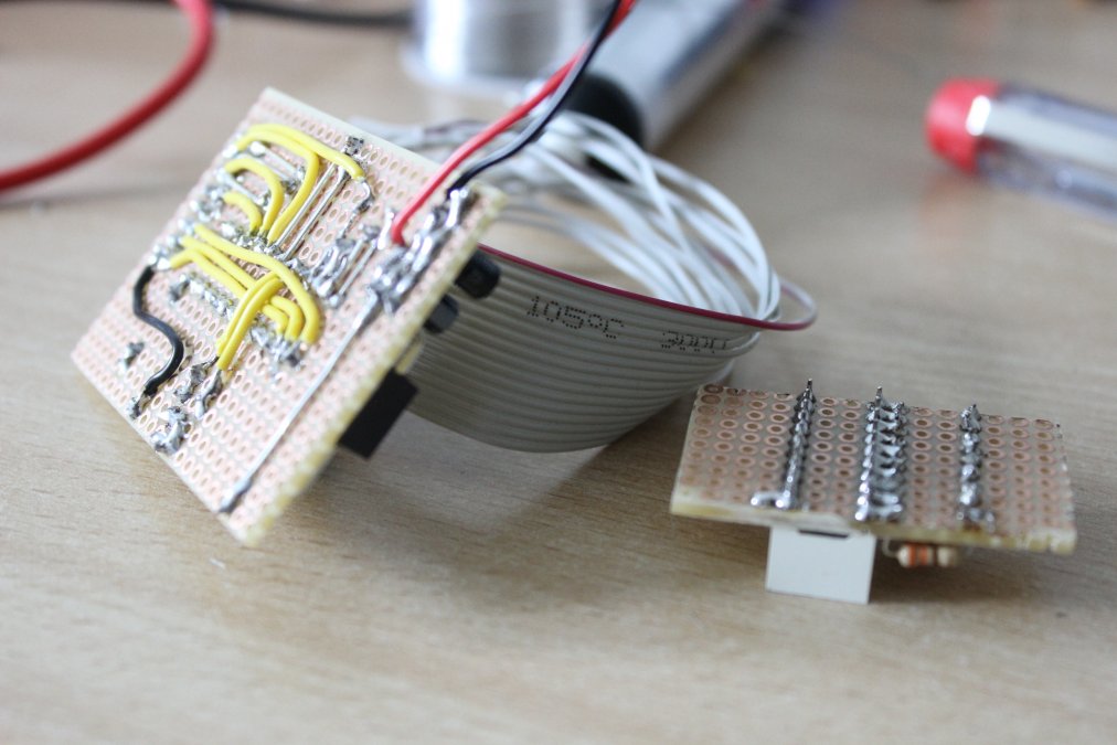
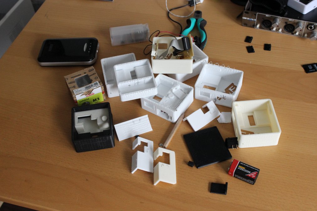
Now the last missing thing is a nice, fancy case, to go and play outside.
My idea was to add a cool radioantenna to my detector, but i don't own one, and didn't want to order (They are quite expensive! Dunno why.)
If you want to print the case, you'll find the data on thingiverse.com.
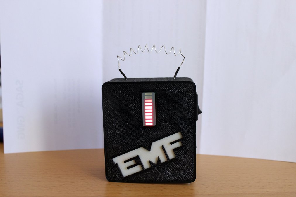
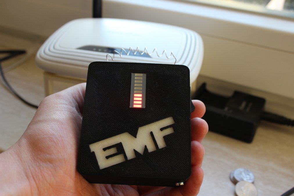
Now it looks like a broken light bulb, but that's okay for me.
The following video shows how i build this detector (in german only):