Mastadon Fuzz - Manly sound for guitars
Exchanging physical stuff is supercool. Why are people not stuck with it? (Maybe because it's not cool to pay your new car with 1.5 million carrots.) I would like to have a cool logodesign for my DIY stuff, but I suck at drawing and a good friend of mine, who is a professional designer, wants to have a very specific effectbox for his guitar, but has no soldering skills. So why not "execute" a classic exchange of these things? I would never pay his hourly wage. This is why I bought this DIY kit (You have to order the knobs extra!!!), waited for delivery and stored the kit in my desk. It's like wine: Store it and wait. To be honest: I had less time and enough other $things to do.
Three months passed by till I deciced to assemble the kit. I bought this thing with a pre drilled case, which floated me into madness, but I will explain this later.
The package contains everything which is needed to build this kit, even a connector for an 9V-battery, which is nearly useless, because there isn't a powerswitch.
The PCB is etched in a good quality, printed and makes the assembly really easy. A manual exists too, so if you have ever soldered before: No problem for you!
But to be honest: I failed at three points:
While I soldered the capacitors (C1-C6, image below) I didn't know where to put them exactly, because the values weren't printed on them. If you are searching for exact these information. Hold on, here are some completed notes. Please don't judge my poor, childish handwriting:

I also added the labeling ot the pots (P1-P4).
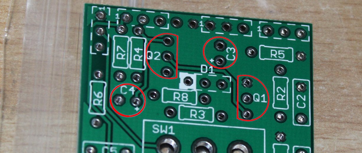
At least you don't have to worry much while soldering, except the orientation of the capacitors (C3+C4) and both transistors (Q1+Q2). Marked red:

On C3+C4 you have to take care on the polarity. Ground is marked with an "-", on the pcb, the source is marked with a "+". So please don't put ground on source, otherwise you will hear a "nice" bang and smell + see some smoke. When you put the transistors in place, just look on the printed shapes on the pcb. You see: Easy!
When you have a look into the manual, you will see how to solder the pots. But I didn't notice, that they are placed upside down at the drawing:
If you finished soldering, it should look similar to this:
My second "W(hat)T(he)F(uck) moment" was while i assembled the LED:
THAT was no fun at all, because the case (Again: I ordered the case, because I thought I can really save some time) wasn't as cool as I thought:
The spot, where the LED should pop out is blocked by the capacitor C3: This poor, tall tower. I really don't know, why you place the hole for the LED on exactly this spot. Maybe I did a mistake, while I assembled the board, but I really don't have clue, where I should have failed.
So to fix this problem, I cut the pins of the LED as short as possible in front of the socket and soldered some wire onto them, then added some shrink tube. On the other end of the wires I re-soldered the pins again and added some shrink tube, because the holes, drilled through the pcb, were to tight, to put the wires directly. At least I had to bend the capacitor to one side, to even add more space.
What a pitty, I really tried to build it really nice and clean. Now it looks like an horrible accident:
The third disillusion was while I placed the pots:
These pots have a "hook" to put them into the case and prevent them from rotating inside the case, while you turn the knobs. And now please guess, what's missing inside the case: Jeah! Right! The notches! This is why the pots come out not slightly straight. I fixed it with some washers. But why?
But when considering the price, the DIY kit really is okay and works (btw: The sound is awesome).
Maybe I'm a bit spoiled and the default musician (the target group) just smiles, adds some washers and is okay with it. Should I ever build this again, or a smiliar DIY kit, I'm now being warned and don't have to fail on these things again.
**Supplement** (2016-07-02): Boris couldn't wait to get back home, when I gave him the device t work. But later this day, when he tried it out, the result was: Nothing. No sound, wether on bypass-mode or active. So he gave it back to me the next day. The kit has been delivered with two different audiojacks: One was mono, the other stereo. So there is this 50/50 chance to solder the right pin at the stereojack. Aaaaand of course, I hit the other one. I soldered the right pin and it was done. How it sounds like? I just tried some stuff with my bass. Listen:
PS: This is how the device came back, after only 12 hours in the hand of a graphicdesigner:


